
|
|||||||||
First Steps in Amateur Radio, 1962 - 64 |
|||||||||
|---|---|---|---|---|---|---|---|---|---|
as ZS1ZG (later as ZS6XT) |
|||||||||
Click Broad Arrow for Links page. |
|||||||||
|
|
|||||||||
The following radio sets were in my first station. Excellent equipment was available very inexpensively on the military surplus market. |
|||||||||
| WW2 and 1950's/1960's military-surplus radio equipment lent itself very well to modification and repair by the enterprising homebrewer. For those bereft of such skills, though, all is not lost; help is at hand. | |||||||||
| Click to call the Military Surplus Repair Centre toll-free. | |||||||||
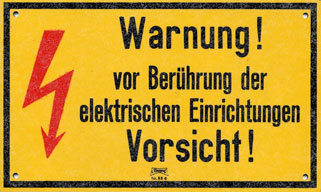 |
Military surplus equipment employing tubes contains lethal voltages.Safety First! |
||||||||
|
|||||||||
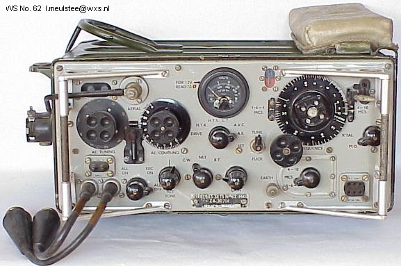
The Wireless Set No. 62: 1.6 to 10 MHz, up to 5W CW, up to 1W AM |
|||||||||
| Wireless Set No. 62 was a portable/mobile transceiver developed by Pye in about 1945. Use: general purpose for vehicle and ground station, but suitable as a man pack and animal pack. Frequency range 1.6-12MHz. RF output 1W. MO and crystal control. R/T and CW. Range up to 25 miles. Replacement for No. 22 Set. (Used instead of the famous No. 19 set in some applications.) The Calibrators Crystal No 10 (ZA32171) was an essential accessory for amateur use. There is a mint No. 62 Set in the collection of the Duxford Radio Society. | |||||||||
| The Duxford Radio Society offers an excellent history of the WS62. | |||||||||
|
|||||||||
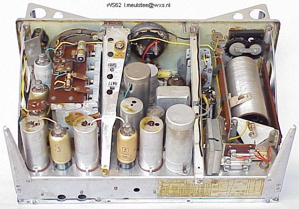
The Wireless Set No. 62, inside view |
|||||||||
| Powered by 12V DC, the No. 62 set had a miniature dynamotor under the chassis. This was replaced in 1963 by a transistorised power supply. (How I wish now that I could have got hold of one at the time!) | |||||||||
 |
|||||||||
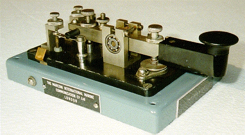
The Marconi 365A Straight Key |
|||||||||
| I received this magnificent key as a gift when I earned my first amateur licence (ZS1ZG) in November 1962. It gave me many hours of enjoyable CW QSO's, chugging along at 15-18 wpm, until I closed my station in 1967 and relocated to Europe. I passed it on to a good friend who had just been licensed. I still use a straight key in my current station - a JRC KY-3A maritime key, acquired in 1989. | |||||||||
|
|
|||||||||
 |
 |
 |
|||||||
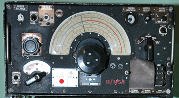
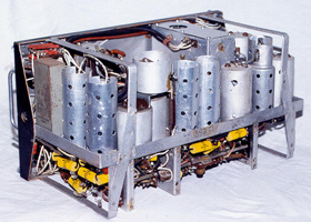
| The Royal Air Force R1155 LF/HF Receiver Manual | The R1155, inside view | The T1154 LF/HF Transmitter | |||||||
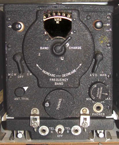
| The R1155 is a British LF/ HF superheterodyne receiver covering from 75kHz to 18.5 MHz in 5 bands, with D/F (Direction Finding) and homing functions. It was developed by Marconi's Wireless Telegraph Co. in 1939. The R1155, and its companion T1154 transmitter, were fitted to many WW2 R.A.F. aircraft such the Avro Lancaster and the DeHavilland Mosquito. Huge quantities of R1155's came onto the surplus market after the war, and were snapped up eagerly by hams and SWL's all over the British Commonwealth. Prices were of the order of a few dollars. The receiver is small and light, and has a good feel when tuning in stations. It is fairly sensitive and reasonably stable, although drifting somewhat during warm-up. |
|
Jerry Proc offers an excellent history of the T1154/R1155 equipment. | |||||||
|
|
The FuG
10 Aircraft Radio System was the German Luftwaffe equivalent to the
T1154/R1155 - but was of far superior construction.
FuG10 auf deutsch |
||||||||
|
|
|||||||||
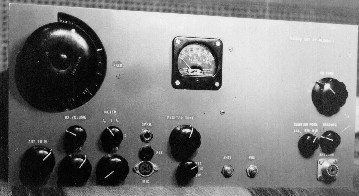
An Improved HF Station Receiver System: the U.S.N. RAX-1 with the R.A.F. GEE RF Unit No. 27 |
|||||||||
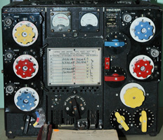
| Both the R1155 and the PCR3 suffered from several operational shortcomings in amateur service; poor image rejection on the higher bands, indifferent frequency stability and lack of bandspread. In 1963, one of my fellow-students, an avid SWL, offered me a General Electric US Navy RAX-1 (CG-46116) receiver in a trade; I jumped at the opportunity. The RAX-1 had several unique characteristics, including excellent frequency stability, construction and performance. For example, it used fairly conventional circuits operating off 160V DC, lowering noise and extending tube life by comparison to other designs utilising 250V B+ (HT). | |||||||||
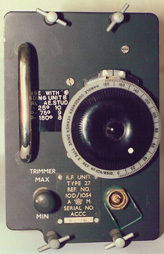
| The CG-46117 receiver covered 1.5 ~ 9 MHz, with a 915 kHz IF. To allow 20-metre operation, I converted an RF Unit No. 27 (as used in the R.A.F. R1355 GEE receiver) into a down-converter with a crystal-controlled L.O. and high-side injection. The reworked RF Unit, with its EF50 RF stage and mixer, had excellent sensitivity and strong-signal handling. At a signal frequency of 14.0 MHz, the IF output was 9.0 MHz. The resulting double-conversion superhet completely eliminated the image problems which had plagued its predecessors in my shack. | |||||||||
 |
 |
||||||||
|
The GE RAX-1 Receiver |
The RF Unit No. 27 | ||||||||
|
|
|||||||||
 |
|||||||||
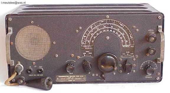
The Pye PCR "Communications Receiver" |
|||||||||
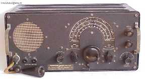
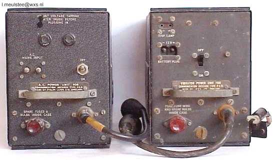
| The PCR series was manufactured by Pye, and was a forces welfare receiver. Frequency coverage: LW, MW and short-wave 5.5-18MHz. There are three versions, the initial PCR (also known as PCR1) and later PCR 2 and PCR 3 which have no internal loudspeaker and a different frequency range. The receiver is powered by a separate mains Supply Unit Rectifier No. 17 or 12V DC Supply Unit Vibratory No. 8. | |||||||||
| I bought a brand-new PCR3 at a surplus store in Pretoria for £5 (about $15), and modified it quite heavily. Mods included a crystal IF filter, high-transconductance RF stage, BFO and S-meter. After all that, the set was still not quite good enough for amateur use on the higher HF bands. The receiver had no bandspread tuning, so the whole 20m band covered 5 mm on the dial! The single-conversion design with a 465 kHz IF had very poor image rejection above 10 MHz. And the frequency stability was unacceptable for CW or SSB. Thus, I ended up selling my PCR to an SWL buddy, and using only the R1155 as a station receiver. View the PCR3 in my station. | |||||||||
|
|
|||||||||
Early Attempts at HF "Portable" |
|||||||||
(this is no IC-703!) |
|||||||||
|
|||||||||
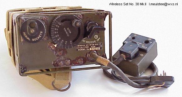
| The Wireless Set No. 38 Mk.II, front view. The WS 38 Mk II was a manpack transceiver developed in 1942. Use: short range Infantry communication. Frequency range 7.4-9.2MHz. VFO control. RF output 0.2W. R/T only. Range: up to 1 mile using long 12ft rod. This set has unique design features using only 5 directly-heated tubes. Standard WW2 set. (A friend of mine and I got our licences together. We bought a pair of WS 38's, retuned them to 40m, and got all of 1/2 mile range on the ground!) | |||||||||
|
|||||||||
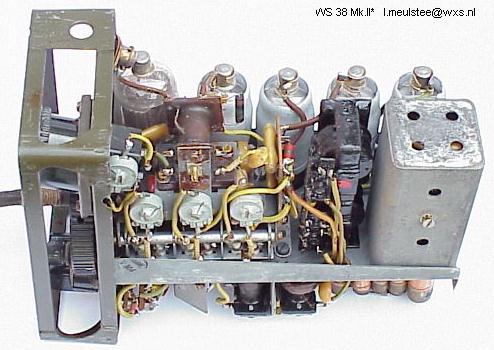
| The Wireless Set No. 38 Mk.II, inside view. Note the ATP4 RF PA tube (left) and four ARP12 tubes. This particular set is in unmodified condition, and has even the original decoupling capacitors which are just visible in the right bottom corner. The set uses reflex circuits (simultaneous amplification of RF and audio) to reduce the tube count. Junction Box No. 2 (front view, on right) was used for connecting the combined 150/3V battery (four point plug in foreground) and headphones/throat microphone to Wireless Set No. 38 Mk. II. A six point plug and cable connects the No. 38 Set to the junction box. (My friend and I could not find the original battery packs, so we improvised using "D" cells and 67.5V "B" batteries. The batteries ended up costing us more than the radio sets!) | |||||||||
|
|
|||||||||
|
|||||||||
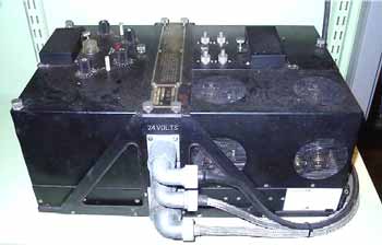
| The TR1196 HF R/T Set. For communication between R.A.F. Bomber Command aircraft and airfield control when returning to base, the aircraft was fitted with the TR1196, which replaced the earlier TR9. The TR1196 was a four-channel HF set, consisting of four units: a crystal-controlled transmitter (left), a crystal-controlled superhet receiver (right rear), a 24V dynamotor P.S.U. (right front) and a channel selector equipped with a stepping solenoid (centre). The channel selector was integral with the mounting base; other units plugged into it. The stepper rotated the channel switch shafts in the transmitter and receiver. The set was AM-only. The transmitter had a separate P.A. tank circuit for each channel, with a rotary inductor. The four knobs and the tuning lamp on top of the transmitter were used for output tuning; power output was about 3 watts AM. The four tuning shafts, one per channel, can be seen on top of the receiver. The rectangular Tx and Rx crystal covers are also visible. The receiver had about 1 µV sensitivity; it was fitted with a squelch circuit. The set used the same 4-button control head as the VHF sets (British TR1143 and U.S. SCR-522). Later in the war, as these VHF sets became more available, they replaced the TR1196. (In 1963, I crystalled up a TR1196 on a few 40 metre CW frequencies, and used it with a long-wire. Due to the poor selectivity and lack of frequency agility, however, this set did not stay in my shack for very long.) | |||||||||
| Another TR1143 site. | |||||||||
|
|
|||||||||
|
|
|||||||||
|
|
|||||||||
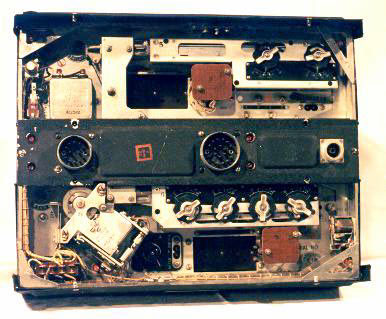
| The SCR-522 VHF R/T Set. Radio sets SCR-522 and SCR-542 were based on the R.A.F. TR1143. These radio sets were intended for use in aircraft, and provided two-way radiotelephone communications between aircraft in flight and between aircraft and ground stations. Operation may take place on any one of four crystal-controlled channels lying within the frequency range of 100 to 156 MHz. Remote control only is provided, via a control head in the cockpit. Radio set SCR-522 operates from a 28-volt source and uses dynamotor PE-94-A. SCR-542 operates from a 14-volt source and uses dynamotor PE-98-A. Radio sets SCR-522 and SCR-542 differ only in the primary power supply voltage and the dynamotor unit used. (I took my "First Steps" on 2 metres in 1963, with an SCR-522A. After building a mains PSU for the set, I gave the soft 832 tubes a decent burial and reworked the BC-625 transmitter completely. With a 5894 PA, modulated by a pair of 6V6GT's in a special triode connection, and a 6252 driver, the transmitter delivered 35W AM to a 50-ohm load. FT-243 crystals in the 8 MHz range put the transmitter on around 145 MHz. I also made the BC-624 receiver tuneable over the range 144 to 146 MHz, and replaced the 9003 RF and mixer tubes with 6AG5's. This improved the sensitivity considerably. The fruit of all this effort was a number of QSO's with my friend 5 km away. He was using a Heathkit "Twoer", a.k.a. "Lunchbox".) | |||||||||
|
|
|||||||||
Test Equipment |
|||||||||
The Oscilloscope Project |
|||||||||
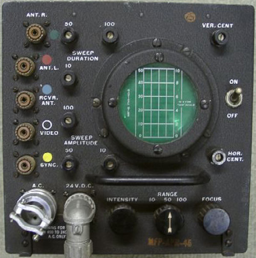 |
At one point, I needed
an oscilloscope in the shack. Being a typically
impecunious engineering student at the time, I felt that a surplus
conversion would cost the least, and still look fairly decent.
I found a new BC-929 Indicator (part of the SCR-729 or AN/APN-2 radar beacon system) at the local surplus dealer. The store even carried a conversion manual, and a 220V 50 Hz power transformer with all required windings for a BC-929 oscilloscope project! I gutted the unit completely - except for the CRT and its associated control circuits, and the HV rectifier and filter. Two weeks later, I had a functional oscilloscope with a reasonably linear timebase and approximately 1 MHz vertical bandwidth. Total outlay was less than $20. The instrument served me very well in a variety of homebrew and surplus-based projects. |
||||||||
The Crystal Calibrator |
|||||||||
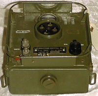 |
When I was first
licensed in South Africa, in 1962, the Radio Regulations stated that a
holder of an amateur radio licence was required to have in his station a
"frequency-measuring device with stability and accuracy equivalent to that
of crystal control". In practice, this meant a crystal calibrator.
Our local surplus store obligingly came up with a Calibrators Crystal No 10 (ZA32171). This unit is designed to be used in conjunction with the Wireless Set No. 62, and is connected to the set via a 3-wire cord. This instrument uses battery-filament miniature tubes, and thus has low power consumption. |
||||||||
The Field-Strength Meter |
|||||||||
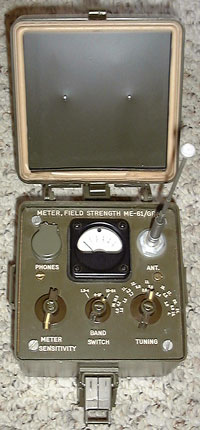 |
I had the good fortune
to acquire a brand-new U.S. Army
ME-61/GRC
field-strength meter at the Miami, FL
Hamfest in 1998. The meter has since been sold to a collector. Radio amateurs use a reflectometer or RF power meter to tune up a transmitter (that is, when an auto-tuner is not doing the job for them!) It is often convenient, though, to check the radiated field strength with an instrument such as the ME-61/GRC. The field-strength meter can also be used to chase down "RF in the shack". When tuning up a military or portable radio with an attached antenna, it is often not possible to hook up a reflectometer - particularly if there is no 50-ohm point in the antenna system. In such cases, the field-strength meter is the only tune-up aid. The ME-61/GRC covers 1.5 to 24 MHz in 3 ranges. It is fitted with a "PHONES" jack, which can be used to hear the demodulated envelope of the received signal. In situations where the transmitting antenna is located some distance away, the operator can monitor the signal at the transmitter location to verify that the system is radiating a signal. Department of the Army Technical Manual TM 11-5820-453-10, "Operator's Manual, Radio Sets AN/GRC-87 and AN-VRC-34", shows the ME-61/GRC as a component of these systems. |
||||||||
|
|
|||||||||
A Step Forward, 1964 - 67 |
|||||||||
as ZS6XT |
|||||||||
| Shortly after starting work at Racal, in Pretoria, South Africa, I designed and built a hybrid 20m SSB/CW transceiver using military-surplus and commercial parts. This radio featured a unique circuit topology, in which a single RCA-7360 beam-deflection mixer tube served as receiver front-end and transmit balanced modulator. The rig had only 11 tubes; power output was 65W PEP. | |||||||||
 |
|||||||||
| I took a few breaks from the transceiver project; one of them was the 1964 Johannesburg Festival special-event station ZS6JFS, at Zoo Lake. | |||||||||
|
|
|||||||||
Next Steps, 1976 |
|||||||||
as VE3DGY |
|||||||||
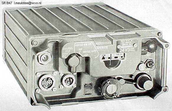
STATION RADIO B47-B48 |
|||||||||
| Station Radio B47 was developed for communication between tanks and to infantry, equipped with corresponding man-pack equipment. B47 sets replaced Wireless Sets No. 88 AFV and No. 31 AFV. A complete station comprised Transmitter Receiver B47 with internal vibrator power unit and Aerial Tuning Unit No. 8. | |||||||||
| Station Radio B47 has a frequency coverage of 38-56 MHz in 181 channels with 100 kHz channel-spacing. The set has continuous tuning with a film scale marked at every channel. Similarly as with the C42/C45, an internal two-stage crystal calibrator and a centre zero tuning meter are used to accurately set each channel. The RF output is 0.5 watt and about 0.01 watt at "low power". The set operates on 24 volts, 12 volt units have been made on a very limited scale. (I used this set on 6m FM; we had a group in Toronto which used to meet on 52.525 MHz, using various U.S., British and Canadian military VHF sets.) | |||||||||
|
|||||||||
Transmitter-Receiver B47: 38-56 MHz, FM (15 kHz deviation), 0.5W |
|||||||||
|
|||||||||
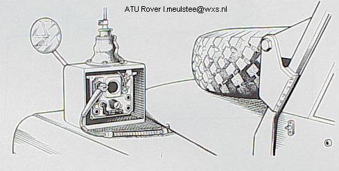
Aerial Tuning Unit. |
|||||||||
| Both C42/C45 and B47/48 use a standard 8 ft vertical rod aerial. To match the 8ft aerial to a set an aerial tuning unit (TRFA, "Tuner Radio Frequency Aerial") is used. Each set has a different type of tuning unit, depending on the frequency range and the RF power. The aerial tuning unit is mounted in a hermetically sealed die-cast case. This permits mounting e.g. on the vehicle's front wing direct below the aerial base. (I fitted the 8 ft. rod aerial to my A.T.U., and bolted the assembly to an electrical cable-tray on the roof of a 20-storey Toronto apartment building in which I was living at the time. Fortunately, there was no need to go outside to retune, as we were operating only on 52.525 MHz.) | |||||||||
|
|
|||||||||
| To prevent military radio equipment from falling into enemy hands, press: | |||||||||
|
|
|||||||||
Side Steps: Repeaters, 1976 - 1986 |
|||||||||
as VE3DGY, then VE3DGY/W4 |
|||||||||
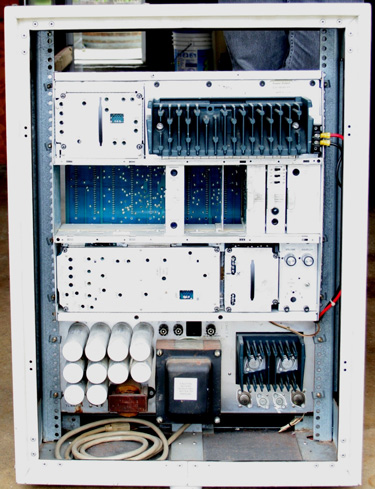
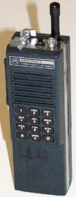
| In Toronto, most of the "action" above 30 MHz was (and still is) on 2m and 70cm FM. Remaining in the spirit of surplus conversion, we built up VHF and UHF FM radio systems consisting of retired PMR (land-mobile) base stations, mobiles and portables. As my Ham friends and I were "in the business" professionally, we had excellent access to such equipment. For maximum reliability, all the radio gear we deployed was 100% solid-state. Starting out with Pye Telecom and Systcoms radios, our efforts culminated in a Motorola Micor C63RTB base-station repeater (West Palm Beach, FL 147.315 MHz). I reconfigured the station for repeater service, and de-rated it from 60W to 30W. We installed this system in 1984, and it is still listed. User radios included Motorola HT-220's and MT-500's which I assembled from piece-parts, or refurbished. Some old mobile phones were also successfully converted into 2m transceivers and UHF repeaters. | |||||||||
 |
|||||||||
| Motorola Micor C71RTB base station. Click for Micor info. | |||||||||
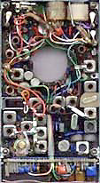
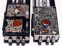
| Motorola HT-220 with DTMF front. | VHF HT-220 board, "PL" deck. | HT-220 interior: 5W VHF PA board (l.) Main board (r.) | |||||||
 |
 |
 |
|||||||
| HT-220 photos courtesy Michael Wright. | The Repeater Builders' Technical Info Site | ||||||||
| FM, LMR & Ham Radio | |||||||||
|
|
|||||||||
A Further Step, 1993 - 1999 |
|||||||||
as AB4OJ |
|||||||||
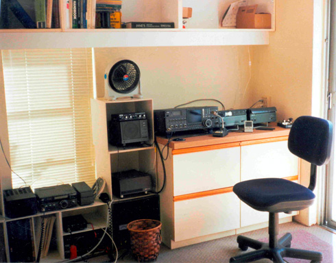
An ICOM "Classic" Station |
|||||||||
| In 1993, I acquired Icom's "King of Beasts" - the famous IC-781. This HF transceiver was the first amateur HF radio fitted with an internal CRT display, which presented all the operational settings as well as a real-time Spectrum Scope (panadaptor). The IC-781 drove an IC-2KL 500W solid-state linear amplifier, followed by an IC-AT500 automatic ATU. The three units were interconnected to provide a self-tuning, 500W HF station. The photo below illustrates my Icom "Classic" station in Boca Raton, FL as it was from 1995 to 1998. An IC-729 (HF + 6m) and various FM transceivers can also be seen. | |||||||||
|
|
|||||||||
| The IC-781, IC-2KL and IC-AT500 are often discussed on my friend Frank W3UHF's excellent Icomclassic forum. | |||||||||
|
|
|||||||||
The Latest Step, 2016-17 |
|||||||||
as VA7OJ/AB4OJ |
|||||||||
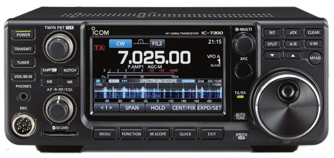
THE NEW ICOM IC-7610 AND IC-7300 DIRECT-SAMPLING SDR HF/6m TRANSCEIVERS |
|||||||||
| Various Icom HF radios found a home in my shack, starting in 1989 with an IC-725. | |||||||||
| My current station incorporates an IC-7610, an IC-7300 and a Yaesu VL-1000 (Quadra) amplifier. | |||||||||
| The IC-7610 or ic-7300 can be selected as an exciter for the amplifier. | |||||||||
| The antenna is a Cushcraft R8, overall height 15m | |||||||||
| Please visit my Icom Page, and the Icom Information and FAQ site. | |||||||||
 |
|||||||||
|
|
|||||||||
|
Pictures and descriptions by kind permission of Mr. Louis Meulstee, PAØPCR |
|||||||||
TR1196, BC-929 pictures by kind permission of Mr. Paul Bodifee, PE1NGZ |
|||||||||
Icom IC-7300 picture courtesy Icom Inc. |
|||||||||
| If you have comments or suggestions, please e-mail me. | |||||||||
|
|
|||||||||
|
|
|||||||||
Copyright © 1999-2022 A. Farson. All rights reserved. |
|||||||||
Last updated: 08/11/23 |
|||||||||