 |
Excellent dynamic microphone and receiver elements (inserts) are frequently available from military-surplus sources and telephone suppliers, and are quite inexpensive. These elements are specifically designed and optimised for radio and wireline voice communications, and meet all applicable ITU and military standards. Typical examples are the Electromagnetic Type No. 1 & 2*, made in England by S.G. Brown Ltd. (nowRacal Acoustics). The mic element is red, with a white flash across the face; the receiver element is green, also with a white flash. Variants are red or green without the flash, as applicable, or gold-coloured. The red element with a black flash is an electret. The mic element has a star-shaped pattern of holes; the receiver has three holes in a triangle.
*Click to download data sheet.
The impedance of the S G Brown mic and receiver elements is typically 300Ω at 1 kHz. (Some variants are 2.4 kΩ). The output of the 300Ω mic element is 2 mV into 300Ω (or 4 mV into high-Z) for speech at 2.5 cm (1") distance. This is somewhat higher than the output of the popularHeil HC-4 and HC-5 elements.
The frequency response of the mic element rises 7.5 ± 1 dB/octave over the range 200 - 3400 Hz. This is somewhat comparable to the Heil HC-4.
The accompanying data sheet lists complete details of these elements.
It is easy to assemble a dynamic hand microphone by mounting a surplus element inside a "retired" LMR or amateur mic housing. The possibilities are limited only by one's imagination and the availability of parts, the only condition being that the element should fit securely inside the housing and have a reasonable acoustic seal against the front shell.
Complete lightweight handsets fitted with a pressel (PTT) switch also come up in surplus from time to time. These often incorporate the elements described above, and can easily be modified to interface with an Icom (or other) amateur transceiver.
The surplus mic cord is typically terminated in an 8-pin "Foster" plug. Blocking and decoupling capacitors are added as shown in Fig.1, which is a typical schematic of a "roll-your-own" mic or handset compatible with Icom radios.
| |
The author obtained an E F Johnson LMR mic housing and cord at a local hamfest, and re-worked it as discussed above. Fortunately, the S G Brown element was an almost perfect fit in the front shell of the housing. Fig. 2 illustrates the completed mic. Note the high-quality Neoprene cord and 8-pin "Foster" plug wired for Icom radios.
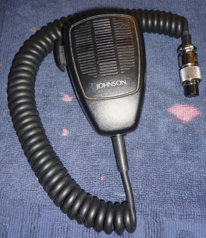 |
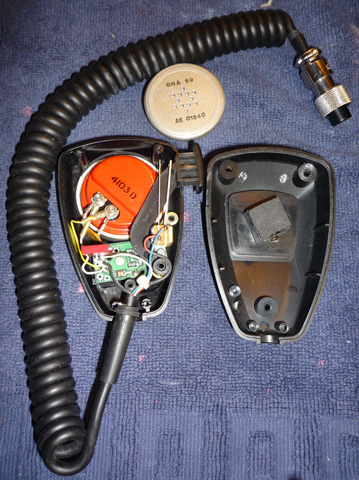
Fig. 3 is an interior view of the microphone. The red S G Brown mic element is an almost perfect fit in the front shell; a ring of foam tape provides an acoustic seal. A block of foam rubber on the inside of the rear shell holds the element in position.
The red rectangular 1 µF non-polarised blocking capacitor can be seen, as well as an 8.2 nF (8200 pF) decoupling capacitor across the element terminals. A 5 mm ignition wrench fits the terminal nuts on the element. A spare element (2.4 kΩ, gold-coloured) is also shown.
 |
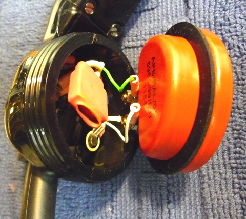
The author purchased a British Ministry of Defence NATO handset, manufactured by Racal Acoustics, from a dealer in the UK. Such handsets frequently come up on popular auction sites, at reasonable prices. This handset is made of moulded black nylon (dark green is also encountered) and is fitted with the mic and receiver inserts as described above. Fig. 4 shows the modified handset with cord and 8-pin "Foster" plug (replacing the original U229 6-pin military plug). Note the large pressel switch (PTT grip).
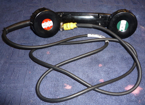 |
Fig. 4 is a disassembled view of the mic housing. Note the 1 µF non-polarised blocking capacitor enclosed in heat-shrink tubing. Decoupling capacitors were not added initially. The original U229 plug was cut off, and the cord wired per Table 1. Other types of handset may be wired differently, of course.
| Colour | Description | Pin # |
|---|---|---|
| Green | Mic Hot | 1 |
| (Shield) | Mic Sh | Shell |
| White | Mic Rtn | 7 |
| Red | Rec Hot | 8 |
| (Shield) | Rec Sh | Shell |
| Blue | Rec Gnd | 6 |
| Black | PTT Gnd | 6 |
| Orange | PTT | 5 |
 |
The author tested the mic and the handset on 20m and 17m SSB, with several local and US stations. The radios used in these tests were an IC-7700, an IC-756Pro3 and an IC-7200. The radiosettings used were the same as for the Heil HC-5. MIC GAIN and COMP were adjusted for a mid-scale ALC reading and 6 dB compression on voice peaks. As the S G Brown elements have higher output than the HC-5, MIC GAIN at 10 - 11 o'clock and COMP at 11 - 12 o'clock were found adequate.
The audio reports received were generally quite favourable, with the comment that the audio was very crisp and articulate but somewhat strident - rather like a military HF-SSB radio system.
The total outlay for the mic and handset was approx. CAD 40 (USD 33) - quite a bargain, considering the results.
Modifying Clansman Lightweight Headsets for Amateur Use, by Martin Ehrenfried G8JNJ
I would like to thank Brian Austin GØGSF for his contribution to this article.
Copyright © 2007-2020 A.Farson VA7OJ/AB4OJ (including images). All rights reserved. Last updated: 07/27/2020.
![]()