 |
|
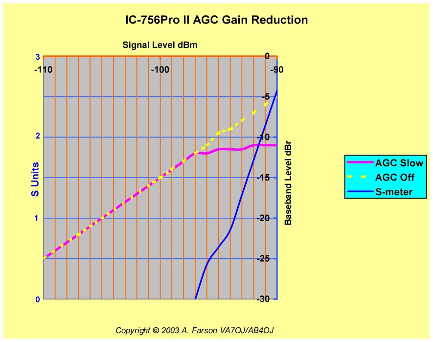
These AGC measurements are the result of a collaborative effort involving George, W5YR and myself. Our objective was to measure the IC-756Pro II's AGC threshold, i.e. the point at which the AGC just starts levelling the baseband (audio) output with increasing RF signal level at the receiver input.
IC-756Pro II S/N 26XX. Freq.: 28499.000 kHz USB. BW = 2.4 kHz, Preamp off, NR off, NB off, Twin PBT neutral (SFT = 0), RF Gain at 100%. HP8640B signal generator set to CW, 28500.000 kHz, LOCK on, minimum output, and connected to ANT 1. ANT 2 terminated with 50 ohms. Sinadder 3 SINAD meter connected to SPKR jack as baseband level meter.
Baseband level setting: With ANT 2 selected, no signal, AGC Slow, adjust AF Gain until SINAD meter in reads -40 dBr (0 dBr = 774 mV) noise in "Flat dB" scale.
Preliminary AGC On/Off correlation test: Switch to AGC Off. Verify that baseband level does not change.
Select ANT 1. Set HP8640B output to -110 dBm. Record baseband levels for AGC Slow and AGC Off, and S-meter reading for AGC Slow.
Increase HP8640B output in 1 dB steps. Record readings as per Step 3 above.
Take special note of the measurement point at which the AGC Off baseband level first exceeds that for AGC Slow. This is the actual AGC threshold (knee). The corresponding RF input level is -96 dBm.
Note that the S-meter starts reading as AGC starts levelling the baseband output. As the S-meter is driven from the AGC line, it is a reliable AGC threshold indicator (Levelling starts at S0.5.)
Repeat Steps 3 and 4 until the RF input level reaches -90 dBm.
Derive chart from recorded readings.
MDS (signal just discernible by ear): -134 dBm (0.04 µV) measured at 28.5 MHz with Preamp off and BW = 2.4 kHz. The AGC threshold is at -96 dBm (3.5 µV) with Preamp off. This is approximately 28 dB above MDS. There is thus a range of 28 dB from the noise floor to the point where AGC just starts to level the receiver gain.
NR was switched in and out at the AGC threshold to check whether enabling NR would vary the AGC gain reduction. Toggling NR had no effect on the AGC.
The IC-756Pro II RF Gain control effectively raises the AGC threshold by applying a bias voltage to the AGC line to reduce the gain of the 1st IF amplifier. Levelling takes place when AGC voltage exceeds the bias. This is observable on the S-meter; AGC action commences when the signal is sufficiently strong to move the S-meter above the reading corresponding to the setting of the RF Gain control.
The above chart will confirm that there is no AGC action for input power levels < -96 dBm. The significance of this is that the gain-controlled first-IF amplifier is running "wide open" for input signal levels below -96 dBm. As discussed in the reference, this AGC threshold has been chosen to minimise the degradation of system noise figure by ADC quantisation noise at low RF signal levels.
"HF Radio Systems & Circuits", Sabin & Schoenike, editors. Noble, 1998, pp. 145-148 (AGC Design); pp. 341-342 and Fig. 8.10 (Digital AGC Methods). Get excerpts (PDF)
Copyright © 2003 A. Farson VA7OJ/AB4OJ (including images). All rights reserved.
Last updated: 09/25/2019
![]()