 |
The IC-7700, IC-7800, IC-7850/7851 and IC-7610 are equipped with a "Digi-Sel" tracking preselector (one in the IC-7700, one per receiver in the IC-7800 IC-7850/7851 and IC-7610). The Digi-Sel Unit is a module which is placed between the RF BPF group and the RF preamplifier group (except in the case of the IC-7610, where it is located ahead of the RF BPF group). This location was selected to place the narrower filter (Digi-Sel) after the wider filter (RF BPF), in accordance with good RF engineering practice. The Digi-Sel covers the range 1.5 - 29.999999 MHz.
Note: The RF preamplifiers (Preamps 1 and 2) are locked out when the Digi-Sel is activated.
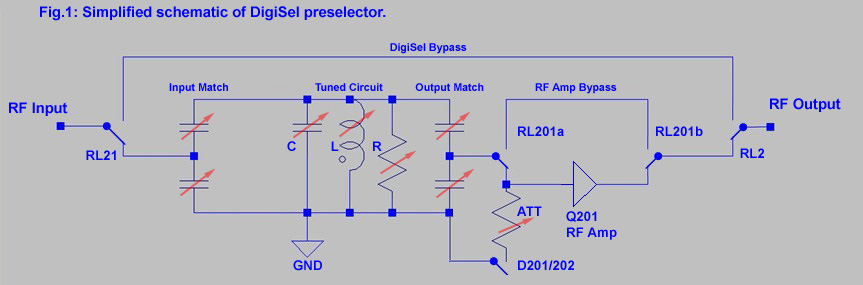
Fig. 1 is a simplified schematic of the IC-7700 Digi-Sel. The Digi-Sel is a one-pole tracking preselector employing a single high-Q tuned circuit, which is matched to 50Ω by capacitive dividers at the input and output. A single-ended Norton-type feedback amplifier (Q201) in the output signal path can be switched in or bypassed as required, to offset the insertion loss of the tuned circuit. This amplifier is optimised for linearity, so as not to degrade system IMD performance. An attenuator is switched in at the amplifier input (via diodes D201/202) for gain trimming. The L and C values of the tuned circuits, and the divider C values, are selected by relay chains. The Digi-Sel tracks the receive frequency, but can be manually tuned via the front-panel [DIGI-SEL] knob.
|
|
Fig. 2 is a photo of the Digi-Sel Unit. The L components and relays can be clearly seen; the RF amplifier, with its feedback transformer, is on the top edge. The RF input and output connectors, and the bypass jumper, are on the right edge.
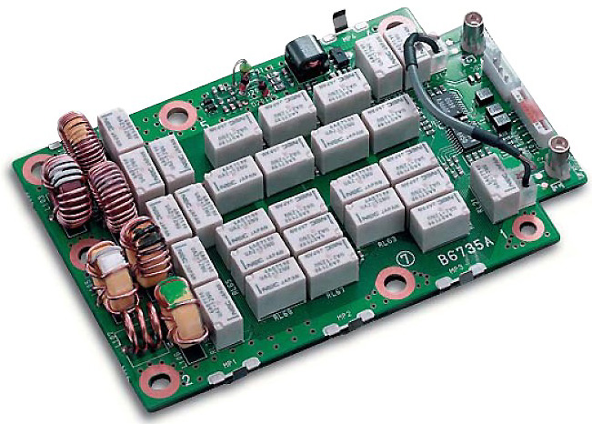 |
Fig. 3 is a partial block diagram. The received HF signal passes though the RX BPF group (BPF or LPF). The filtered signal is then fed to the Digi-Sel Unit, and either goes through or bypasses the Digi-Sel (Digital Preselector) filter. When the Digi-Sel function is activated, the RX signals are passed through the Digi-Sel input relay (RL21) and narrow bandwidth filter (D_SEL BPF) which filters out unwanted signals with its sharper frequency response. The filtered signals are amplified as required by the RF AMP (Q201) which offsets the insertion loss of the D_SEL BPF, then passed back to the RF Unit via the Digi-Sel output relay (RL2). The RX signal at the Digi-Sel output is then passed on to the RF Preamp on/bypass relay (RL1003).
 |
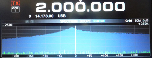
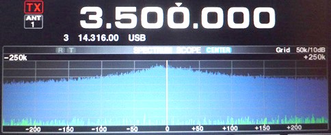
Bandwidth and Insertion Loss/Gain Measurements: The Digi-Sel preselector will attenuate signals well removed from the frequency on which it is peaked. The bandwidth and insertion loss/gain were measured by applying band-limited noise to the IC-7700 ANT1 input from an RF noise generator followed by a LPF with fc = 30 MHz. The attenuation at f0 ± 250 kHz, and the insertion loss/gain at f0 , were measured on the IC-7700 spectrum scope (f0 = receive frequency). Fig. 4 is a typical characteristic curve; Figs. 5 and 6 are typical screenshots, taken at 2 and 3.5 MHz respectively. Table 1 gives the results for the MF/HF range 1.5 ~ 28 MHz.
 |
 |
 |
| f0 MHz | Attenuation in dB at fo ± 250 kHz | Insertion loss/gain in dB at f0 |
|---|---|---|
| 1.5 | 35 | 2.5 |
| 2 | 30 | 2 |
| 3.5 | 20 | 1 |
| 5 | 20 | 0 |
| 7 | 15 | 1 |
| 10 | 10 | 0 |
| 14 | 6 | 1 |
| 18 | 7 | 3.5 |
| 21 | 5 | 4 |
| 24 | 3 | 5 |
| 28 | 2 | 3 |
Effect of DIGI-SEL Control Rotation: Rotating the [DIGI-SEL] knob fully clockwise or anti-clockwise shifts the frequency-response peak by +10 or -10 kHz respectively (at f0 = 2000 kHz). Thus, the manual tuning range is ±10 kHz (20 kHz total).
Effect of Digi-Sel RF Amplifier on IMD3 Dynamic Range (DR3): As mentioned above, the RF amplifier has been optimised for linearity so as not to degrade the receiver's overall IMD performance when inserted. This was verified by measuring IMD3 dynamic range (DR3) at a frequency where the Digi-Sel exhibits insertion gain, indicating that the amplifier is in circuit.
DR3 was measured in CW mode, at 500 Hz IF bandwidth, by applying two test signals at 21.000 and 21.010 MHz from a pair of RF signal generators . The generator outputs were fed via fixed attenuators to a hybrid combiner, and thence via a step attenuator to the IC-7700 ANT1 input. The IC-7700 was tuned to the lower (20.990 MHz) and upper (21.010 MHz) IMD3 products in turn. The 2-signal power level was then adjusted for 10 dB (S+N)/N as measured on a baseband level meter connected to the speaker output, and DR3 derived by subtracting MDS from the power of one of the two equal test signals for the "Digi-Sel off" and "Digi-Sel on" cases.
The measured DR3 value for Δf = 10 kHz (averaged over both IMD3 products) was 100 dB with Digi-Sel off, and 102.5 dB with Digi-Sel on. This suggests that there is no significant IMD3 degradation due to the RF amplifier, and that a secondary effect may be occurring due to the reduction in reciprocal mixing noise with the Digi-Sel in the signal path.
Examples: The following scenarios illustrate situations in which the Digi-Sel reduces co-channel IMD3 due to nearby HF broadcast stations.
An 80m amateur signal f0 = 3600 kHz and two 75m broadcast signals f1 = 3200 kHz, f2 = 3400 kHz. Both f1 and f2 will pass through the selected 3 - 4 MHz BPF. One IMD3 product falls at (2f2-f1) = (2*3400) - 3200 = 3600 kHz = f0. The Digi-Sel attenuates the 3200 kHz signal by ≈ 35 dB and the 3400 kHz signal by ≈ 17 dB. If we average these attenuation values, the IMD3 product is attenuated by ≈ (3 * 25) = 75 dB.
A 40m amateur signal f0 = 7150 kHz and two 41m broadcast signals f1 = 7300 kHz, f2 = 7450 kHz. Both f1 and f2 will pass through the selected 6 - 8 MHz BPF. One IMD3 product falls at (2f1-f2) = (2*7300) - 7450 = 7150 kHz = f0. The Digi-Sel attenuates the 7300 kHz signal by ≈ 10 dB and the 7450 kHz signal by ≈ 15 dB. If we average these attenuation values, the IMD3 product is attenuated by ≈ (3 * 12) = 36 dB.
Link: Digi-Sel Insertion Gain & Bandwidth.
References:
IC-7700 User Manual, pp. 1.10, 5-18.
IC-7700 Service Manual, pp. 3-1, 9-3, 10-16.
Copyright © 2010-2017 A. Farson VA7OJ/AB4OJ (including images except where noted). All rights reserved.
Last updated: 09/25/2019
![]()