
COPYRIGHT: This piece is a condensed version of Technical Correspondence, QST, June 2002, p.68. et. seq. This condensation may not be distributed or republished, without express permission of the authors, or of ARRL. This short version is provided for web posting through specific web sites, previously authorized. You may provide links to sites where this piece is found. You may give copies to other amateurs, in printed or soft form. You may not rewrite or reproduce it, in any way, nor may you remove the copyright paragraph. Refer also tocopyright notice below.
Shortly after Icom’s IC-756 Pro HF/6 meter transceiver was introduced into the US, one of the authors observed that signals within the upper IF bandwidth could be heard, even though they were well outside the lower IF filters.
These signals took on a lot of characteristics, and weren’t observed by all amateurs. These signal artifacts were variously described as ‘phantom signals’ or ‘ghosts’ or ‘rumble’, and were so variously reported, as to be completely rejected by ICOM.
Now that we know their source, it makes perfect sense that their reported characteristics varied, and that some folks didn’t hear them at all. This brief paper describes both a source and correction for what we now identify as “The Noise Blanker Drive-Signal Leakage Problem.”
Early reviews by RSGB and DLARA, and ARRL remained within their structured testing schemes, for consistency. Casual operating comments in the review text for the most part failed to identify this particular anomaly, even though it very likely degraded the results of some intermodulation distortion tests. The problem is dependent on input signal levels and density, and quite variable. Standardized tests require a certain amount of simplicity, in order to be both meaningful and repeatable.
To be clear: The Noise Blanker Drive signal in every 756PRO is leaking into the main audio channel. You can hear it, using headphones. You WILL hear it, when the right amount of interference is present. You cannot hear it in a speaker, although it contributes interference. You cannot hear it in the rear panel audio, on acc1; it is injected after that point. Headphones plugged into the front panel reveal the problem. The ICOM sp21 speaker does not have sufficient LF response to permit hearing the problem.
Once you notice this leakage, you’ll also discover that it is present even underneath the signals you are trying to copy, both on CW and SSB. On SSB, it sounds like a growly-rumbly sound, under the signal of interest. The signal is actually INTERFERING WITH ITSELF. On CW, it sounds like thumps and bumps…like muted or low-pass filtered key clicks.
Tune off that loud signal of interest and you still hear the growly-rumbly, thumps or bumps, as long as the loud signal remains within the 7.5KHz wide upper IF. This led to reports of “Shadow Signals” or “Ghosts” in the radio. With a single data signal in the passband, it will appear to be a mirror image of that signal, but lower in pitch.
The Probable Cause: K1KP did the schematic analysis. The performance characteristic led quickly to the only point in the audio chain where the rumble could be introduced, and to a pretty good first guess as to its source.
Our working hypothesis was that the rumble signal was actually the AM detected version of the entire 455kHz IF passband, which is used in the Noise Blanker to derive a gate signal, used to blank noise pulses. It was surmised that this signal was coupling into the 8V supply rail, and getting coupled into the output of U311, which is a two-stage low level audio preamp and voltage controlled gain stage.
How to hear it: Find a band that has a lot of strong signals. Tune the rig so that there are several strong signals within 7.5 kHz of the indicated frequency.Turn the AF gain control all the way down. Set your RF/SQL pot to RF+SQL.(In the SET menu, OTHERS, RF/SQL, select RF+SQL.) Set the squelch control so that the receiver is muted, by turning the RF/SQL control clockwise until the RX LED goes out.
Connect a set of headphones with good LF response to the front panel jack. (HeilProSet was used by the authors.) Slowly advance the AF gain control until you hear a faint ‘pop’ at about 7:30. At this point you should be able to clearly hear the low-frequency rumble. The rumble sounds like an AM detected (muffled) version of all the signals in the roofing filter passband. If you have difficulty hearing it, try tuning in a loud signal, setting the audio gain around 9-10 o’clock, and then tune off that signal. You should hearits ‘shadow’, still in your headphones. Once identified, tune the loud signal back in again…you can hear the ‘shadow’ UNDER the signal of interest.
If you experiment with various controls on the radio, you will find that the NB signal is not very sensitive to the exact tuning. It is unaffected by the AF gain control setting, but is eliminated when the AF gain control is all the way off. It is also swamped out by band noise, when the audio is run up high. The problem appears to be worse when the Noise Blanker is turned on.
Although this may seem to be a trivial artifact, when chasing DX on 20 meter SSB, or under contest conditions, with a full upper IF of very strong signals, it results in muddy, hard to copy SSB, and weaker being obscured by strong adjacent channel signals. On CW, the noise floor is full of pops, bumps and clicks which make weak signals difficult to copy.
Confirming the cause, proposing the fix: It was not possible to get scope probes on the audio circuit, because the key components lie beneath the DSP unit. So we did a Gedanken experiment. We theorized that U311, the first audio stage, WAS the source of the leakage, and that its 8V supply rail, which also powers the NB noise chain, was the culprit.
K1KP identified 10 ohm resistor R316 and 100µF capacitor C316 as the decoupling for the variable gain portion of U311. N2EA decided to install a 1000µF capacitor across C316. If the noise changed materially, that would prove the 8V rail was the source.
Not only did the noise change materially, it was reduced enough that it is no longer of concern. Having proven the concept, we contemplated more elegant solutions to produce a clean 8v rail for the audio chain.
The IC-756Pro II decoupling components are changed in both the NB and the audio stages, and are larger than those in the PRO. There is no room to contemplate installing the changes in the PRO. We considered using a 7808 regulator, fed from the 14V rail to power the audio channel, but that’s more complex than the single 1000µF cap, and poses another mounting problem. Ultimately, we elected to keep it simple, and stay with the experimental capacitor.
Caveat: This is fine work on surface mount (SMT) devices. It challenged the vision and tools of N2EA. If you are not experienced with surface mount electronics, we recommend you hire a pro to do it for you. This should be quite simple for anyone who works regularly with SMT boards; a one-hour bench charge should more than cover the work.
The Modification: You will need a 1000µF 16V electrolytic capacitor (Radio Shack #272-958), and some #30 insulated wire-wrap wire (Radio Shack #278-502). Prepare the capacitor by clipping the leads very short. Leave about 1/8 of an inch on each end to solder the fine wire to. The capacitor leads themselves are too large to solder directly to the pcb pad.
Prepare two pieces of wire, about .75” long, by stripping 1/16” from one end and 1/8” from the other. The capacitor can be mounted to the PCB using double-faced foam tape strips (Radio Shack # 64-2344). You should cut a piece of foam strip roughly equal to the size of the capacitor. It is recommended that you have the service manual available, to aid in component location.
Remove all power and other cable connections to the rig. Turn the rig upside down and set it on its top on a soft cloth on your workbench. The front panel of the rig should face you.
Make sure you are using a wrist strap to ground yourself to the rig and prevent any damage from static electricity. Remove the bottom cover by removing the 6 screws in the bottom and the two on each side. Loosen the two handle screws by 4 or 5 turns. Remove the cover and set it aside.
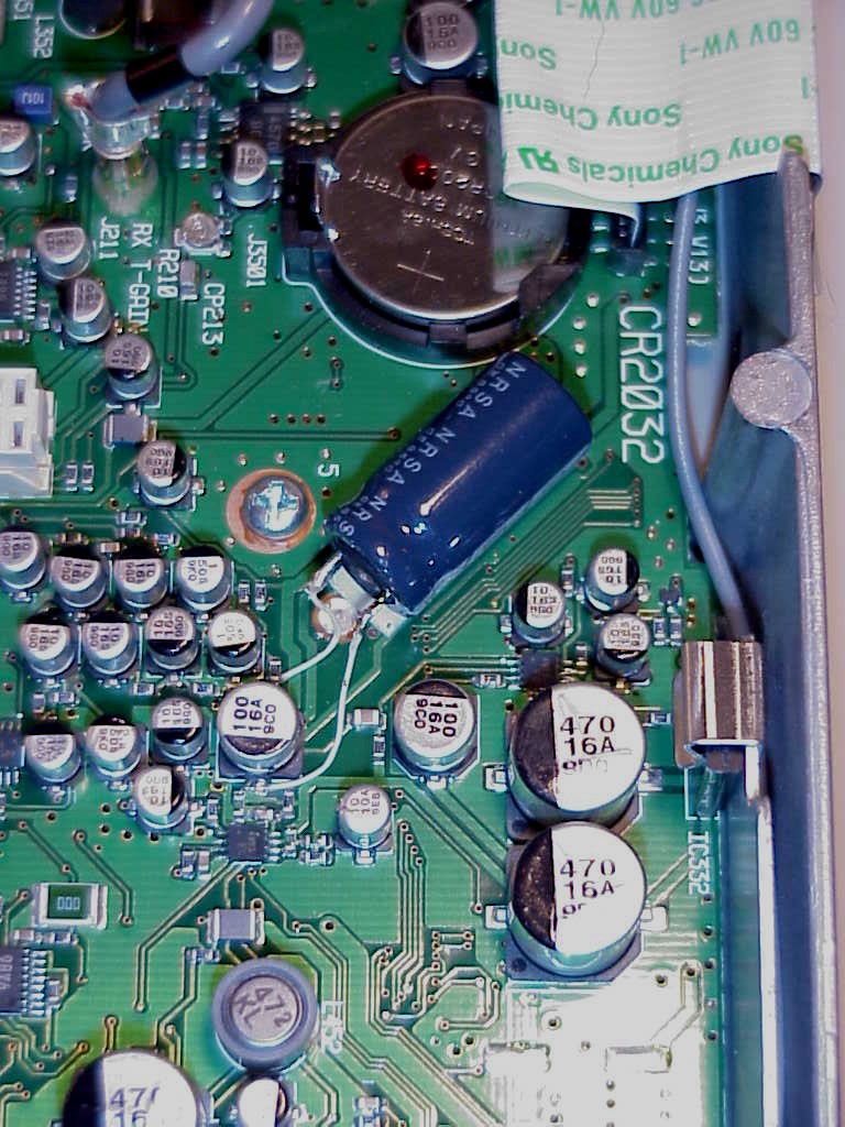
On the right side of the rig you will see the MAIN board. The DSP unit lies above the audio stage of interest. This is the large shiny metal shielded assembly on the MAIN board. It is socketed. Gently remove the DSP unit by lifting it straight up off the MAIN board. You may need to rock it back and forth a bit to get it off. Set the DSP unit aside, in a safe place.
Under the DSP unit, you will see seven capacitors in two rows. The .jpg photo shows the 1000µF capacitor installed on the mounting tape. C316 is located about1/2" below and left of that tape, with wires tack soldered to each terminal. Note that the negative side of this capacitor is toward the front panel.
 |
![]()