|
|
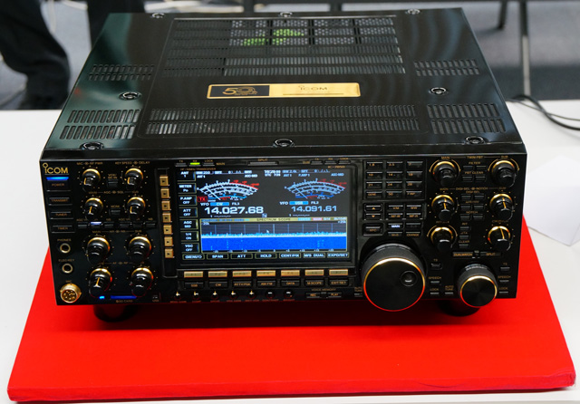
On 14 November 2014, Icom Inc. hosted a presentation on the new IC-7850 for attendees at APDXC 2014 (Asia-Pacific DX Convention, 2014). We were also treated to a hands-on preview of two IC-7850's which were set up in the conference room. Icom engineering managers and staff were in attendance to address questions posed by the audience.
The following is a summary of the PowerPoint presentation material. For the first time, we can present some technical insights and performance figures for Icom's new flagship transceiver.
The IC-7850 and IC-7851 received FCC and IC certification on 15 January 2015. FCC ID: AFJ361500, IC: 202D-361500.
VFO Tracking Feature:
Allows the operator to tune the Main and Sub VFO's synchronously by rotating the MAIN tuning knob. This feature facilitates diversity operation.
Firmware Ver. 1.40, released
30.04.2021, is now downloadable from the Icom Japan Global website.![]()
The Ver. 1.40
Release
Notes describe the features added by V1.40 and previous firmware releases.![]()
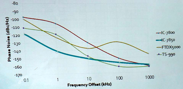
Extremely low phase noise
Effectiveness of Optimum Roofing Filter (64 MHz, Bandwidth = 1.2 kHz).
15, 6, 3 and 1.2 kHz roofing filters fitted to both receivers
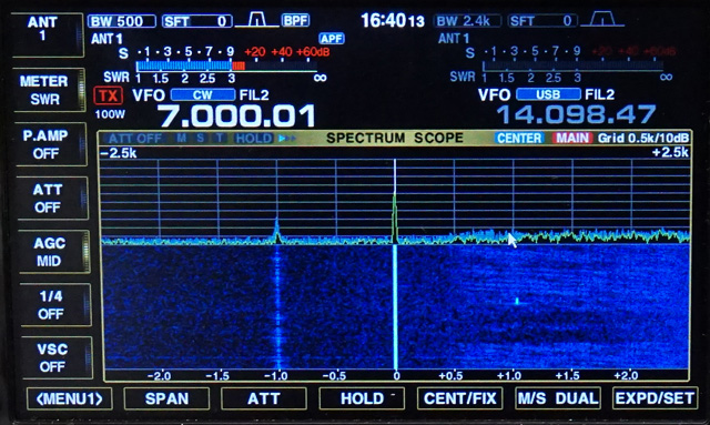
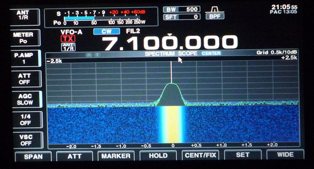
FFT spectrum scope is much faster, much wider and has higher sensitivity (and much narrower minimum RBW).
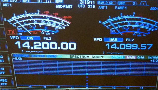
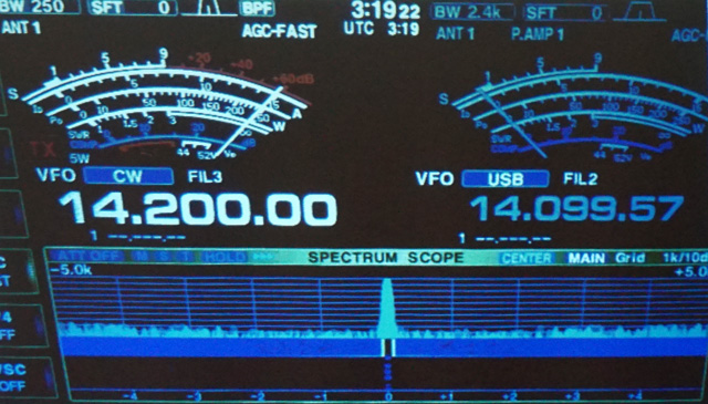
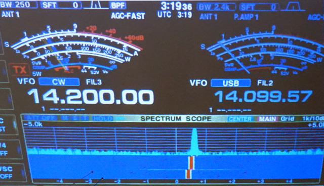
You listen to a signal from a CW station.
The signal is weak (no indication on S-meter).
A local station starts calling CQ on the same frequency. His signal is very strong; S9 + 60 dB.
You ask the station to QSY; how far should you ask him to move?
| IC-7800 | 8 kHz |
| TS-990 | 5...7 kHz |
| IC-7850 | 300 Hz |
 |
 |
 |
 |
| RMDR Table | RMDR dB | |||
|---|---|---|---|---|
| Offset kHz | 1 | 2 | 5 | 20 |
| Radio | ||||
| IC-7850 | 111.6 | 115.9 | 118.6 | 122.9 |
| IC-7800 | 78.2 | 87.2 | 99.2 | 112.2 |
| TS-990 | 83.0 | 88.4 | 100.8 | 117.9 |
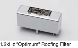 |
FL-483 and FL-484: Bandwidth = 1.2 kHz at 64 MHz. This
filter has been optimized for low passive IMD.
| Manufacturer | Purpose of filter | Reason |
|---|---|---|
| Others | To improve RMDR | Poor LO spectral purity |
| ICOM | To improve IMD | -- |
| DR3 | at Spacing | ||||||
|---|---|---|---|---|---|---|---|
| Radio | Filter BW | 1 | 2 | 5 | 20 | kHz | |
| IC-7850 | 15 kHz | 100 | 101 | 104 | 114 | dB | |
| 1.2 kHz | 99 | 105 | 111 | 113 | |||
| TS-990 | 15 kHz | 75 | 79 | 90 | 108 | ||
| 270 Hz | 87 | 91 | 100 | 106 | |||
Displays finer resolution
Displays information faster
Lower noise floor displays weaker signals clearly
Dual scope for Main and Sub receivers
Narrower minimum resolution bandwidth (30 Hz)
| Radio | IC-7850 | IC-7800 | TS-990 |
|---|---|---|---|
| Analysis method | FFT | Swept/filter | FFT |
| Span range kHz | 5...1000 | 5...500 | 5...500 |
| Max. resolution, pixels | 1 | 20 | 11 |
| Max. sweep speed, sweeps/sec. | 29 | 4 | 11 |
| Display dynamic range, dB | 100 | 80 | 80 |
| Noise floor, dBm | -137 | -126 | -117 |
| Operation on display | Mouse | Mouse | Touch panel |
| Dual scope (Main/Sub) | Yes | N/A | N/A |
 |
 |
ALC input (0 to -4V nominal, negative-going, adjustable, identical to ALC port on IC-7700/7800) and compatible with amplifiers supporting this voltage range
Selectable reed-relay or MOSFET SEND Relay (keying-line) interface, identical to that in IC-7600/7700/7800
Adjustable TX Power Limit by band
Adjustable TX Delay (RF onset delay), identical to that in IC-7800 V3.00/3.01, IC-7700 V2.00/2.10 and IC-7600 V2.00
Dedicated, private CI-V port for IC-PW1 (by unlinking REMOTE and USB/LAN CI-V ports and assigning separate CI-V addresses) - no more IC-PW1 data collisions!
My full IC-7851 Test Report (including NPR with 1.2 kHz roofing filter)
Replacing the PA FETs in the Icom
7851, by Dave Wilson AA0RS![]()
IC-7850/7851 Firmware V1.40
Cumulative
Firmware Release Notes![]()
RS-BA1 V2.40 with link to manuals![]()
RC-28 Firmware V1.02 (prerequisite for use of
RC-28 with IC-7850/7851 Firmware V1.10 & higher, and RS-BA1 V2.XX)![]()
IC-7300 and IC-7850/51 USB Port Setting Manual V1.0
Introducing the IC-7850 50th Anniversary Edition - video
The IC-7851 on 20m - video
IC-7850 vs. IC-7800 RMDR characteristics - video
All data and images courtesy and copyright © 2014-2021 Icom Inc. (except where noted). Editing & page creation: A. Farson VA7OJ/AB4OJ.
Last updated: 04/30/2021
![]()