![]()
 |
![]()
 |
![]()
 |
![]()
 |
![]()
 |
 |
 |
![]()
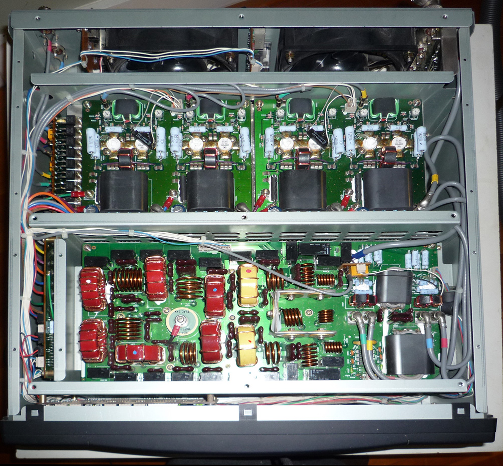
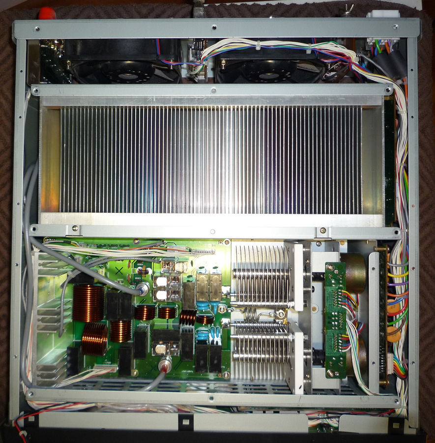
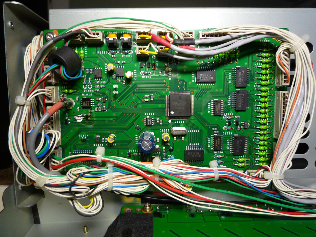
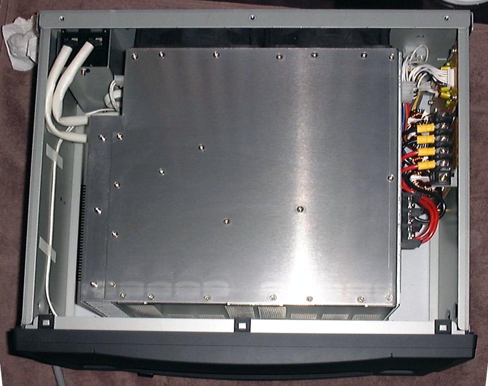
VP-1000 Repair Procedure, by Bert Garcia N8NN
Quadra 1003 Error (PA Imbalance) Troubleshooting, by Richard Notton G3ZOE
Guidelines for Noise Suppression with the Yaesu Quadra, by Peter Jackson VK6KXW
![]()
![]()
Copyright © 1999-2023 A. Farson VA7OJ/AB4OJ (including images). All rights reserved. Last updated 11/28/23.